Full Node Details View
Node Anatomy
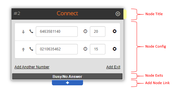
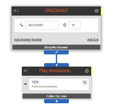
A complex node consists of four sections:
- The node title, displaying the Node Number (important for linking to nodes), node type name
(e.g. “Business Hours”) an
xicon and a yellow tab.- The
xicon can be used to delete a node. - Clicking on the node title allows editing of the node title. However this is not applicable to Start, OCNCC Black Box, or Link nodes. If an empty title is chosen, the default will be selected when saving.
- Clicking on the yellow tab will open the note edit interface. If a note is already present the tab will be replaced by the note block. Clicking away from the note edit interface will save the note data against the associated node.
- The
- The node configuration, displayed in the centre of the node. This section differs depending on the node type. See the per-node documentation for more information.
- The node exits. Node exits are shown in a row, and are given either a name or a number, depending on the node type. Clicking the node exit will focus on the child node coming from that exit
- The add node link, shown below each node exit that may have a node connected to it. Use this to extend the control flow with new nodes and logic.
A node may be selected by clicking anywhere within the node bounds. When doing this, the node will be given a grey shadow visual representation of the selection.
Adding Nodes
To add a new node, use the add node button that appears below the node exit you wish to connect the new node too:
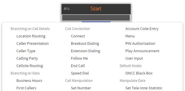
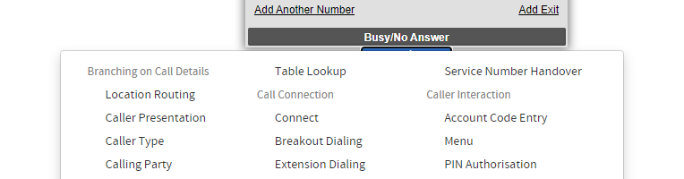
When clicking the add node button the list of available nodes is presented, categorised by the type of functionality. Select the node type you need and the new node will automatically be added to the display. The flow may also be redrawn to accommodate the new node into the graphical layout that the tree graph demands.
Deleting Nodes
Deleting nodes can be done by clicking the x icon in the top right of the node’s display in the
canvas. When deleting a node the node will be removed from the flow and the branch leading to the
node will be removed. The branch connecting to the node removed will have the node addition button
re-added to it.
Deleting a node which has nodes connected to its exits will cause a node dialog to display with options for preserving some or none of its children:
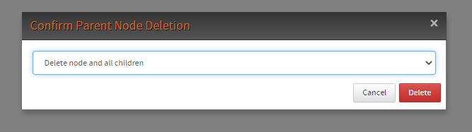
This avoids accidentally deleting an important node in the flow and allows nodes to be excised as required. If the first node is deleted, the Start node will be the only node shown in the flow.
Inserting Nodes
N2FE supports the insertion of flow nodes in between two existing nodes.
Inserting nodes can be done by clicking the pencil icon which replaces the + icon on a node exit when an exit is in use.
When clicking the node insert button the standard list of available nodes is presented:
Selecting a flow node from the insertion list will perform one of three potential actions:
- If the selected node has only one exit, it will be automatically added to the flow view and the following nodes will be attached to the only exit of the inserted node.
- If the selected node has no available exits an error message will be shown to the user and no further changes are made.
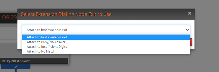
- If the selected node has multiple exits the user will be prompted to choose which exit to attach the following nodes to.